Modernized Arrow electric motor
-
Electric motor
The engine is located in a cylindrical sheath with closed ends heads at both ends. Two square collars / mounting protrusions protrude from each end edge supported by clutch and engine mounting. The engine is attached to the frame with two reverse mounting screws and two reverse dowels. The left end of the engine compartment (around its periphery) has a elongation that allows access to the engine brushes. These cutters are covered with a single-stage coating, which is attached with two fastening screws. Motor engine shaft roofed roof both end and rotates the ball, the skies (whole life changes is hastily). Coupling affixed to the engine shaft on the left at the bottom of the that provides entertainment, accommodation / space, space / space while filling. A small gearbox is attached to the opposite end of the drive shaft, which acts as the drive mechanism. Three threaded grid is driven by the motor portion of the right end and providing terminals incoming galvanise.
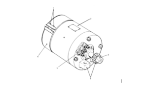
Fig 1 – Electrical Motor
1.Cover Securing Screws; 2. Motor Casing; 3. Gear Pinion (Driver); 4. Supporting/Locating Lugs; 5. Terminal Post; 6. Cover
-
Transmission and gearbox
Transmission / gearbox includes: small (driving) and large (amorously) date of worms and worms wheel of. Gearbox, the small size of the seat belt affixed to Clausen and engine engine is the affixed to the that manage large gears (84 teeth). The large gearbox is equipped with a key and mounted on the right end of the worm shaft. The cast aluminum cover covers all gears to protect the staff while working on the machine. Cover Picanto stamped axial Chanita, which is affixed to the clutch and the side of the engine on the right side. Worm helminth mines integral part of, supported by two plain car (one at the bottom of the PER), which is located in a horizontal hole in Davila and engine mounted on. Helminth tire, which represents a clutch mechanism, the part is a worm and who “holds” the friction clutch bands, clutch levers and աղբյուր. The Clutch is maintained and mounted on a clutch drive.
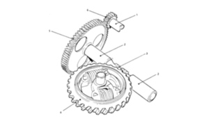
Fig .2.– Transfer and Reduction Gears
1.Motor Drive Shaft; 2. Wormshaft Bearings; 3. Worm; 4. Wormwheel; 5. Large (Driver) Pinion; 6. Small (Driver) Pinion
-
Combined clutch and gear
Combined clutch and drive mechanism consists of the following components: lock washer
Round cast iron plate for collar, unload rim. The plate has a central bore which is reflected in the clutch axis, the top of the sleeve. Two grease ipples in recess holes designed for lubrication inside the clutch mechanism.
- Camera unlock
Small machined steel ring. Release both inside and outside to create cameras. Its inner surface places the lower side of the shoulder block plate. Two round steel fasteners vertically removed from the plate in the bottom of the contract becomes 270º.
* Friction clutch tape
C-shaped thin steel metal tape. The gap in the Strip is included in the two working language placements of the clutch lever. The outer surface of the film has a rib surface and is in contact with the inner surface of the worm wheel.
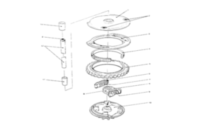
Fig. 3. – Combined Clutch and Drive Mechanism
1.Locking Plate; 2.Grease Nipples; 3. Unlocking Cam Ring; 4. Clutch Friction Band; 5. Wormwheel; 6. Retentive Spring Plungers; 7. Retentive Spring; 8. Left and Right Clutch Levers; 9. Clutch Lever Spring; 10. Driving Disc; 11. Clutch Axis Pin Bushes; 12. Clutch Axis Pin
- Clutch levers and spring
It consists of two levers, the (left and right) that are opposite each other on top of the fitted. Both have a central bore to accommodate the clutch axis. Each lever at the end of the working language, which in normal operating condition rests on the friction clutch strips of two open receiving end. In the assembled state, a compression spring is held between the two interior surfaces of the working languages. At the forefront is held in the collision mechanism, the center of the CLI axis, the axis through which passes Berets in the central holes.
- Worm wheel
Essentially designed steel ring with peripheral level for the formation of worm wheel teeth. Its machined inner surface is placed in a friction clutch belt.
- Disk drive
Polygonal cast-iron steel disc, its lower side is formed gearbox (10 teeth), its center is wells, which includes the lower axis of a pin knot. Two protrusions on top of the drive provide space and housing for the holding Springs. Semicircular protrusion on the lower side of the disk ensures the movement of the entire movement mechanism.
- Spring hold
This heavy compression spring is held between two plenaries that are connected to each other. The ends of the Pistons are of such shape that they are referred to as the leading disk and the plate of the rack.
- Clutch pin and bushings
A round steel tip passes through two bushes of phosphorus bronze. The lower sleeve is located in the drive wheels, while the upper sleeve is wheels the wheels, while the top of the sleeve located in the lock plate in. Coriander the lower part is placed on the Lower Western Lower membrane, while the pin of the upper part of the bone, and the engine mount is located. Axis axis do not rotate the fastening plate with the help of which is affixed to the pairing of the upper part of the site and the engine installed on. Coriander the center along the rash acts as a lubricant channel which serves bread to the axis of the upper part of the oily nape.
-
Anchor Bar
Engine wheels consist of machined flat steel Geodon, which has a transmission of teeth (gear rack), which is developed one of the CDs along its length approximately in half. These teeth clings to the leading apparatus. At the opposite end, a steel sleeve with a knife is attached. The rod supports the bottom casing lengthened and fastened to the surface inside the casing.
Detector slides
Detector of both the slider (top and bottom) is made of flat steel bar from the machinations of the hole in order to occur in the detector legs. Each detector has a two-point, one to determine that the switch button is closed, and the second to determine that the switching button is open. Replace the seat belt open area made open to replace the block free to move on the opportunity, which allows you to open switching from closed knife. GRE during the operation, the detector rails moves inside and outside the lower housing apartheid, which also provides rails support. Plug the last connector affixed to each slide, the front end of the drum, two mounting screws and the fastening plate, using. This, in turn, horizontally aligned with the Connecting Point is connected to the switching stem.
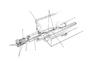
Fig. 4. – Drive Bar and Detector Slides
1.Lower Casing; 2. Detector Slides (Upper and Lower); 3. Pinion (Driving Disc); 4.Drive Bar; 5. Extension; 6. Stop Plate (Detector Slide); 7. Fork end Connectors; 8. Connecting Pins
Editor: Merabi Chaladze
0 Comments